

Musculoskeletal Imaging / Osteoarthritis
Osteoarthritis
Imaging in Osteoarthritis
Several imaging techniques are available to assess osteoarthritis (OA) in natural history studies and clinical trials. Imaging plays a crucial role in monitoring pathologic changes affecting relevant structures around the joint, helping in the understanding of incidence and progression of disease as well as in testing different treatment modalities.
To date, the recommended structural endpoint for disease-modifying OA drugs in clinical trials, by both the U.S. and European regulatory authorities, is the slowing of radiographically-assessed joint space narrowing. Assessment of joint space narrowing and presence of osteophytes may be performed semiquantitatively and quantitatively, with the Kellgren-Lawrence (KL) scoring system and the Osteoarthritis Research Society International (OARSI) atlas classification system been the more frequently applied in OA studies.
However, because radiography is a projecting technique, its sensitivity of detecting changes over time may be affected since the joint space assessed does not cover the entire articular surface for several joints. Also, its specificity is often affected since the joint space may represent by a combination of different structures, as in the tibiofemoral joints (the joint space is represented by both the articular cartilage and menisci).
Although conventional radiography is still the most commonly imaging technique applied in clinical practice and clinical research in OA, magnetic resonance imaging-based studies have revealed some of the limitations of radiography, as discussed below.
-
This is the least expensive and simplest imaging technique to be applied in OA research. Radiographic assessment can determine the joint space width (JSW), considered as an indirect surrogate of cartilage thickness (and also other potential structures such as the menisci in the tibiofemoral joints). Semiquantitative assessment of OA using radiography may be achieved by using the KL scoring system (5) and the OARSI atlas classification system (6).
The KL scoring system is a widely accepted method to define the presence or absence of OA, with the grade 2 commonly used as the threshold. This system has some limitations, particularly when assessing longitudinal progression of disease: the KL grade 3 may include several degrees of JSN, regardless of the extent. To assess progression of structural damage in OA, it is recommended a focus on JSN alone using either a semiquantitative (10) or a quantitative method. The OARSI atlas grades JSW and osteophytes separately, showing better potential and sensitivity regarding longitudinal radiographic changes when compared to the KL scoring system.
Quantitative methods are available to evaluate JSN using either a physical device or a software application, measuring the distance between the projected subchondral bone margins on the image. At the tibiofemoral joints, the femoral margin is defined as the projected edge of the bone, with the tibial margin determined by the software as a bright band (projection of the x-ray beam through the radiodense cortical shell at the base of the tibial plateau). Quantitative methods to assess tibiofemoral JSN demonstrated usefulness when quantifying the responsiveness to change longitudinally (11). The responsiveness of radiographic JSN using automated software was successfully demonstrated using a software analysis of digital knee radiographs, and it was comparable with magnetic resonance imaging in detecting OA progression (12).
-
MRI is able to overcome the limitations of radiographs, and to date it is considered as the reference imaging method to assess the morphology of all intra- and extra-articular structures due to its capability to visualize soft tissues with excellent contrast, providing high-resolution and multiplanar assessment of joints. Several semiquantitative and quantitative methods to evaluate morphology and composition of articular structures are available and were extensively applied in previous OA natural studies and clinical trials. Semiquantitative morphologic whole-organ scoring performed by our expert team of musculoskeletal radiologists in several OA studies has helped in the understanding of the associations of pathology in different structures with incidence and progression of structural damage, as well as with clinical symptoms, especially pain (13-33).
The first scoring system published was the Whole Organ Magnetic Resonance Imaging Score (WORMS), which has been used extensively for more than a decade in a multitude of OA studies world wide (34). Since then, three more whole organ knee scoring systems have been introduced: The Knee Osteoarthritis Scoring System (KOSS), the Boston Leeds Osteoarthritis Knee Score (BLOKS), and the MRI Osteoarthritis Knee Score (MOAKS) as an amalgamate of the WORMS and BLOKS scoring tools (35-37). Some musculoskeletal experts from our team extensively contributed to test the reproducibility and sensitivity to change in OA pathology regarding these available semiquantitative systems, directly participating in multiple scoring exercises, aiming to increase the efficacy of morphologic MRI assessment of the OA joint (38-40). In comparison to previous systems, the MOAKS refined the scoring of morphology of several articular structures, exhibiting very good to excellent reliability for the large majority of features assessed, and to date it is the most recommended tool for semiquantitative assessment of knee OA (37).
All of these scoring systems are based on MRI without intravenous or intra-articular administration of contrast agents, while other systems have been presented that are based on intravenous contrast-enhanced MRI specifically developed for assessment of synovitis in knee OA (17). Semiquantitative systems using MRI are also available for the assessment of hip OA, known as Hip Osteoarthritis MRI Scoring System (HOAMS) (41) and for the assessment of hand OA (42).
-
Quantitative compositional assessment of some articular structures such as the articular cartilage has also the potential to help identifying factors related to incidence and progression of OA (1, 43). Some of these techniques are available in most of clinical MRIs, such as T2 mapping and dGEMRIC (44-47), and have the potential to become markers of the incidence and progression of OA, especially in the earliest stages of disease and could be useful in clinical trials when testing disease-modifying OA drugs.
Joint Space Width (JSW) Quantitative Assessment Using Duryea's Method
We offer a fully quantitative measurement of radiographic JSW, which is a surrogate for cartilage loss. This is a novel software tool is used to delineate the joint margins and make measurements of minimum JSW (mJSW) (48) and location-specific JSW (LSJSW). The method has been validated cross sectionally (48,49) and longitudinally (50,51). The assessment of knee positioning and beam angle is also available. This particular method also produces measurement of the knee alignment angle using the standard posteroanterior or anteroposterior radiographs (52).
-
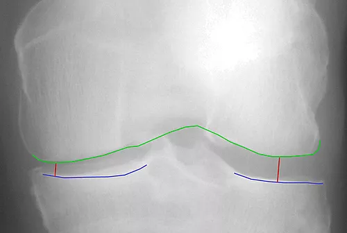
Minimum JSW
-

JSW at fixed locations
-

Knee Alignment
Dynamic Contrast-Enhanced MRI
Dynamic contrast-enhanced MRI (DCE-MRI) enables quantitative assessment of tissue vascularization (53-55). The technique analyzes the temporal and spatial distribution of intravenously administered contrast agents in the microcirculation. Following non-enhanced baseline images, the volume of interest is captured repetitively at high temporal resolution over several minutes. Thereby, the time-intensity curve (TIC) represents the contrast enhancement over time for a certain volume or region of interest (VOI/ ROI).
Quantitative evaluation of TICs includes the assessment of descriptive parameters such as area under the curve (AUC) and peak enhancement (PE) that are associated with regional blood volume. Furthermore, pharmacokinetic models describe a more elaborate analysis of DCE-MRI data requiring additional information, e.g. arterial input function to determine surrogate parameters for regional blood volume or vessel permeability and tissue perfusion. Such mathematic modeling takes into account two compartments in the tissue of interest: The intra- and extravascular compartments.
The rationale of performing DCE-MRI in (osteo-)arthritis is to quantitatively determine parameters of vascularization in bone marrow, joint space and surrounding soft tissue to monitor inflammatory-induced vascular changes (56). Thus, DCE-MRI parameters associated with blood volume and vessel permeability may help to diagnose vascular changes of these compartments in arthritic disease, and to assess therapy response of drugs affecting the microvasculature.
Illustrative Cases
-

Examples of focal chondral defect in the knee joint using high-resolution 3D MRI: A) a partial-thickness defect is depicted at the central medial femur (MOAKS grade 1.0; arrows); B) a full-thickness defect is depicted at the posterior lateral tibia (MOAKS grade 1.1; arrows).
-

Improvement of a focal cartilage from baseline to follow-up. At baseline, the sagittal intermediate-weighted image with fat suppression depicted a full-thickness focal chondral defect at the central lateral femur (MOAKS grade 1.1; arrow - A). At follow-up, a partial-thickness focal chondral defect was detected at the same site (MOAKS grade 1.0; arrow – B).
-

Improvement of a focal cartilage from baseline to follow-up. At baseline, the sagittal intermediate-weighted image with fat suppression depicted a full-thickness focal chondral defect at the posterior lateral femur (MOAKS grade 1.1; arrow - A). At follow-up, the defect was not depicted at the same site (arrow – B).
-

Hip OA: this coronal intermediate-weighted image with fat suppression demonstrates marked thinning of cartilage at the superior and lateral aspect of the femoroacetabular joint, with a bone marrow lesion at the superior / lateral acetabulum (arrowheads), and marked degenerative changes and maceration of the acetabular labrum (arrow).
-
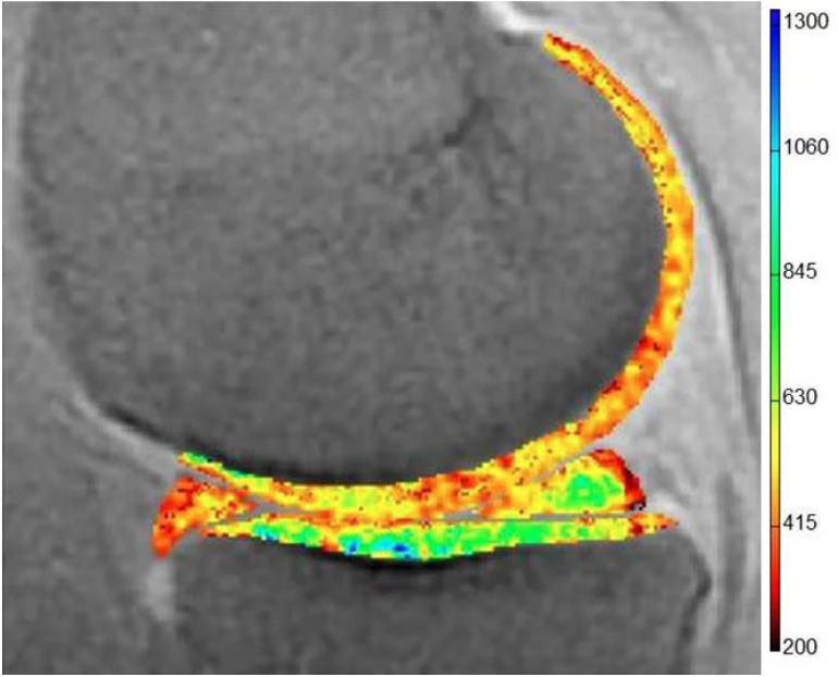
dGEMRIC assessment of the medial tibiofemoral compartment: the superficial and deep zones of cartilage demonstrating a color spectrum from orange to red exhibit low dGEMRIC indices (representing low proteoglycan content within the cartilage matrix). The zones of cartilage displaying a color spectrum from green to blue exhinit high dGEMRIC indices (representing areas of high proteoglycan content).
Hand OA
-
Figure 1
Figure 1 shows an example of a person with hand OA. Mild joint space narrowing and small osteophytes are found in the majority of interphalangeal joints.
OA is also found in the thumb base joints with narrowing and osteophytes in the bilateral CMC1 joints. OA in the interphalangeal and the thumb base can occur separately, but often in combination. Persons with affection of the thumb base will often experience more disability than persons with isolated interphalangeal OA. The phenotype erosive OA is characterized by more severe symptoms, faster disease progression and more inflammation as compared to non-erosive disease.

-
Figure 2
In figure 2, there are good examples of erosive joints (left PIP4, right DIP3 and right PIP2). Remodelling of the joints, which represents end-stage disease, is found in the remaining DIP joints, except left DIP4. The erosive phases are characterized by extensive destruction and remodelling in the subchondral bone, leading to bone marrow lesions, and synovitis, which can be detected on MRI.

-
Figure 3
Figure 3 is a post-contrast T1 VIBE sequence with water excitation covering the 2nd-4th right PIP joints. Whereas small osteophytes are found in the 2nd and 4th PIP joint, the 3rd PIP joint shows complete cartilage loss, large osteophytes, erosive lesions, cysts and bone marrow lesions in the majority of the bone. On the sagittal plane, extensive synovitis is present in the 3rd PIP joint (Figure 4). Synovitis has been shown to be important in hand OA, being associated with symptoms as well as predicting future disease progression.
